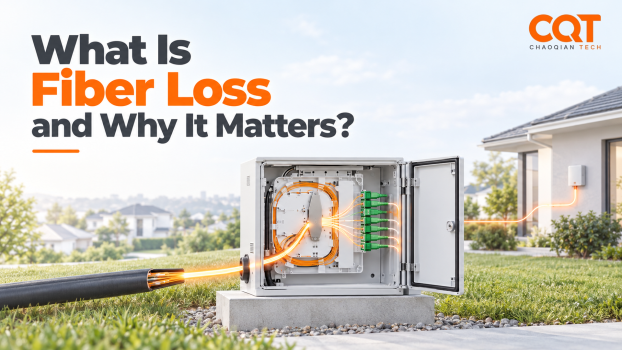
All engineering projects must account for losses and operating tolerances, and fiber-to-the-home (FTTH) networks are no exception. In FTTH networks, it is called fiber loss, or attenuation, which refers to the reduction in optical power as light travels through fiber optics and passes through connections, splitters, and other components. In field practice, managing optical loss attenuation of plays an important role in the cost and reliability of a broadband network deployment. Signal losses will accumulate along the transmission, determining how far a broadband network can reach and how well the subscribers get connected.
In product selection, the optical loss is expressed in decibels (dB) and plays important role when comparing passive optical components. The combined loss of the network must be within the optical power budget limit, as well as leave enough margin space for installation, environmental changes, and future maintenance. This blog-post will explain fiber loss, its cause, and its practical applications in detail, to provide readers with the background needed to make informed decisions.
BACKGOUND KNOWLEDGE: UNDERSTANDING dB, dBm, AND dB/km
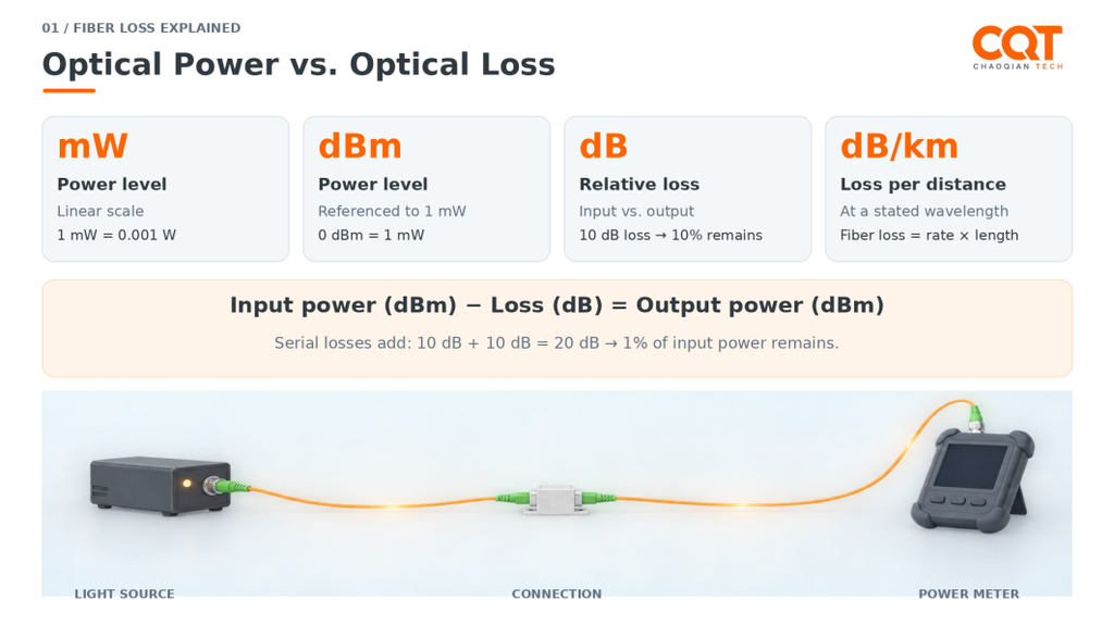
Before diving into product specifications, it is crucial to distinguish the terms. There are 4 relevant units:
- mW (milliwatt): measures optical power on a linear scale. One milliwatt equals one-thousandth of a watt (=0.001W); doubling the value in mW means doubling the optical power.
- dB (decibel): expresses the ratio between two power levels on a logarithmic scale. In loss calculations, it compares the power entering a fiber or component with the power leaving it.
- dBm: expresses optical power relative to a fixed reference of 1 mW. Like mW, it tells how much power is present – not the amount that has been lost.
- dB/m: expresses the attenuation per meter of fiber at a certain wavelength. For telecom and FTTH projects, dB/km is widely used.
In short, mW and dBm describe a power level; dB describes a relative power ratio; and dB/m or dB/km describes attenuation per unit length.
But why do we use dB, a relative term, instead of mW? Yes, the power loss can be expressed and calculated directly in mW, but when it comes to optical loss, the amount is not an outstanding fixed number, it instead depends on the input power. The more it takes, the more it loses, like a “tax rate” being levied upon the light passing through. For example, consider a signal reduction from 2 mW to 1 mW removes 1 mW, while a reduction from 0.2 mW to 0.1 mW removes only 0.1 mW, nevertheless, both represent the same proportional change: half the input signal will get lost.
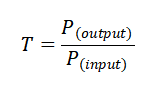
In mathematical equation, we first define the fraction of power after transmission as “T”:
Therefore, the corresponding loss in decibels is defined as:

Here, the input and the output must use the same linear unit, like mW, and the factor of 10 converts the base -10 logarithmic power ratio into decibels. Some commonly used reference points are:
- 0 dB loss: Input perfect equals output, with no loss at all.
- 3 dB loss: Half the input remain.
- 10 dB loss: Only one-tenth remains.
- 20 dB loss: Only 1% remains.
If there are two consecutive passive components, the output of the first component automatically becomes the next input, so their power-retention fractions multiply. No further action is needed, just adding the losses up will get you the total loss amount:

While dB compares two relative power levels, dBm fixes the denominator at 1 mW, allowing a particular power level to be expressed in logarithm:
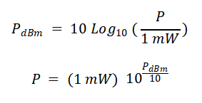
Here, negative dBm doesn’t mean negative optical power, it instead means the actual power is below 1 mW. Conversely, 0 dBm doesn’t mean there is no light, it means the power exactly equals to 1 mW. Some commonly used references are:
- +10 dBm = 10 mW
- 0 dBm = 1 mW
- -10 dBm = 0.1 mW
- -20 dBm = 0.01 mW
In practice, there are four common operations of fiber loss:

WHAT CAUSES OPTICAL LOSS
Optical power decreases as light travels through fiber, crosses connections, and passes through splitters. Some of them is expected, while poor installation or handling can exert additional loss.
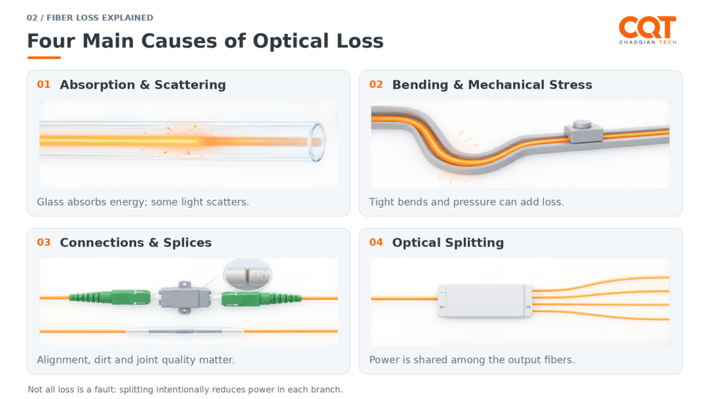
Material Absorption & Scattering: Even a clean, undamaged fiber loses some optical power during transmission because of absorption and scattering. Absorption occurs when the glass and impurities within it absorb optical energy; scattering redirects some light away from its forward path, partly because of microscopic material variations in the glass. These effects accumulate over distance, so a longer fiber generally introduces more loss at the same wavelength. The attenuation also varies with wavelength, which is why a fiber specification should give both the attenuation coefficient in dB/km and the wavelength at which it applies.
Bending & Mechanical Stress: Fiber can also lose power when it is bent too tightly or subjected to pressure. There are two forms of bending are worth distinguishing:
- Macro-bending is a larger-scale bend, such as a tight loop or a sharp turn; an excessive bend allows more light to escape from the guided path.
- Micro-bending involves tiny, minimal distortions, which is often caused by pressure or mechanical stress and may not be visible from outside the cable.
Connections & Splices: Connecting components allow light signal to pass from one fiber into another, and some power may be lost at the juncture. For connectors, dust, oil, scratches, or poor mating can increase loss, making end-face inspection and cleaning important before connection. For fusion splices, the quality of fiber preparation, alignment, and the fusion process affects the result.
Optical Splitting: A splitter proportionally distribute the power available to each output. Unlike bending or environmental contamination, splitting causes an intended reduction of power in PON network, which is designed for distributing the signal from OLT port to multiple subscribers.
- For an ideal equal-ratio splitter, a 1:16 split gives each output one-sixteenth of the input power, approximately 12 dB of loss per output; while a 1:32 split gives approximately 15 dB.
In practice, PLC splitters probably have additional loss beyond their designed power division, so calculations should add the product’s specified insertion loss on top of the theoretical value. A higher split ratio leaves less optical power for each subscriber, making splitter selection a trade-off between the number of branches and the loss the link can tolerate. Yet, on the subscriber’s end, their ONT/ONU modems also have a threshold on the maximum optical power they received. In some peculiar cases, FTTH technicians even install optical attenuator to reduce the signal.
THE BUDGET AND THE COST
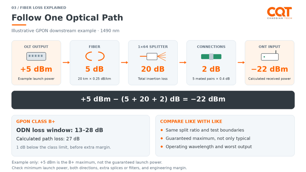
The insertion-loss does not, by itself, make a product the better choice. What matters more is whether the whole passive optical path work together within the required power limits. In a GPON network, the optical line terminal (OLT) sends downstream signals toward subscribers at approximately the wavelength of 1490nm. For Class B+, its specified average launch power is +1.5 to +5 dBm; Class C+ extends this to +3 to +7 dBm. At the subscriber’s home, the optical network terminal (ONT/ONU) must receive enough power to recover the signal while not being overloaded. For a Class B+ ONT, the standard specifies a receiver sensitivity of -27 dBm and an overload level of -8 dBm, providing a useful reference reception window of −27 to -8 dBm. Here, the receiver sensitivity refers to the weakest signal boundary under test conditions, not a recommended operating target. In terms of power budget, for a GPON network, the ODN loss window (the total budget) ranges from 13 – 28 dB for Class B+ to 17 -32 dB for Class C+.
As mentioned in previous paragraphs, the total loss consists of four components: fiber, devices, splitting, and the environment. Fiber optics, for example, may have a maximum attenuation of 0.34 dB/km at 1310nm, 0.25 dB/km at 1490nm, and 0.22 dB/km at 1550nm. In our case, we can assume the network distance to be 20 km. The loss inside passive equipment, like distribution hub or splice closure, may have a loss from 0.4 dB per connection (splice fusion + connecting). When it comes to splitting, an 1×64 splitter may have an insertion loss of 20 dB. Adding all aforementioned losses together would we derive the total loss:

When comparing and selecting passive equipment products, the useful question is not simply “Which one has the lowest loss?” but instead “Which product guarantees the required performance under comparable conditions?” A splitter’s typical value, its maximum value, and a terminal’s measured input-to-output loss describe different things:
- Configuration: Compare the same split ratio, number of stages, and connection arrangement, as a 1×16 module can never be put against a 1×32 terminal.
- Measurement boundary: Confirm whether the figure includes input and output connections, pigtails, internal splices, and any other components on the specified path; otherwise, items may be omitted or counted twice.
- Guaranteed maximum: Use the specified maximum for a conservative design check rather than assuming every unit and output will match the typical figure.
- Wavelengths and outputs: Check performance at the required wavelengths and across all relevant output ports, including the worst-performing port rather than only an average.
- Insertion vs. Return loss: Lower insertion loss means less forward power is lost; higher positive return loss means less power is reflected back. A 55 dB return-loss specification does not mean the product consumes 55 dB of transmission power.
- Installation reliability: Review bend-radius control, strain relief, sealing, and access for maintenance alongside the optical figures, because the enclosure helps protect the performance of the components inside it.
HOW CQT CAN HELP YOUR PROJECT
Zhejiang Chaoqian Communication Technology (CQT) supplies the passive hardware used throughout FTTH networks, including splice closures, distribution boxes, termination boxes, optical cables, and connectors. Alongside conventional products, we offer pre-connectorized options that reduce the need for field fusion splicing. Even if a standard model cannot fit your project, we can customize to make substantial changes, with costs and lead times agreed before production.
Backing our capabilities are more than 70,000 m² of manufacturing facilities, with in-house mold making, injection molding, sheet-metal fabrication, and assembly. Our CNAS-accredited laboratory provides insertion-loss and return-loss testing, alongside mechanical, sealing, temperature-cycling, and aging tests. This allows us to assess both optical performance and the product’s ability to protect the connections inside.

Our customer support continues after delivery. If a product quality issue is confirmed, replacement parts or other remedies can be immediately arranged. To discuss your project, please don’t hesitate on sending us your required capacity, splitter configuration, connector type, installation environment, and optical-loss requirements so that our team can provide an viable solution.