
From Network Planning and ODN Design to Field Deployment
Introduction: FTTH Deployment Is About More Than Getting Fiber to the Premises
On a network diagram, FTTH looks straightforward: start at the OLT, pass through the feeder and distribution network, split the optical signal, and finally reach the ONT at the subscriber premises. In the field, however, that single line on a drawing quickly turns into a series of practical decisions. What split ratio should be used? Where should splice closures and distribution points be installed? How much spare capacity should be reserved? What happens when duct space is limited? Is there enough optical power margin? And when more subscribers are added later, can the original network still support them?
These questions are rarely solved by one product alone. FTTH is a system. Planning, ODN architecture, component selection, field installation and long-term maintenance all affect one another. If one part is overlooked, the problem may not become visible until the network is already in service.
Rather than turning this into another glossary of FTTH terminology, this guide looks at the network from a deployment perspective: what needs to be decided early, which passive components have the greatest impact on installation and maintenance, and where CQT products fit into different parts of the ODN.
1. Start with the End-to-End FTTH Link
A typical FTTH PON network has the OLT at the central-office side and the ONT/ONU at the subscriber side. The passive infrastructure between them is the Optical Distribution Network (ODN).
OLT → ODF → Feeder Cable → Splice / Distribution Point → Fiber Distribution Cabinet or Box (with Splitter) → Distribution Cable → FAT / Terminal Point → Drop Cable → ONT
From an engineering point of view, the ODN can be viewed in three sections. The feeder segment carries capacity from the central office to an area distribution point. The distribution segment extends fiber toward neighborhoods, buildings or streets. The drop segment completes the final connection to the subscriber. Each section places different demands on the components used.
| Network Section | What Matters Most in the Field | Typical Passive Components |
| Feeder | Capacity, branching, sealing and long-term reliability | Outdoor fiber cable, high-capacity splice closure, distribution cabinet / hub |
| Distribution | Splitting, fiber management, expansion and maintenance access | Distribution cable, PLC splitter, splice closure, fiber distribution box |
| Drop | Installation speed, limited space and subscriber activation efficiency | Drop cable, terminal box, connector, pre-connected terminal |
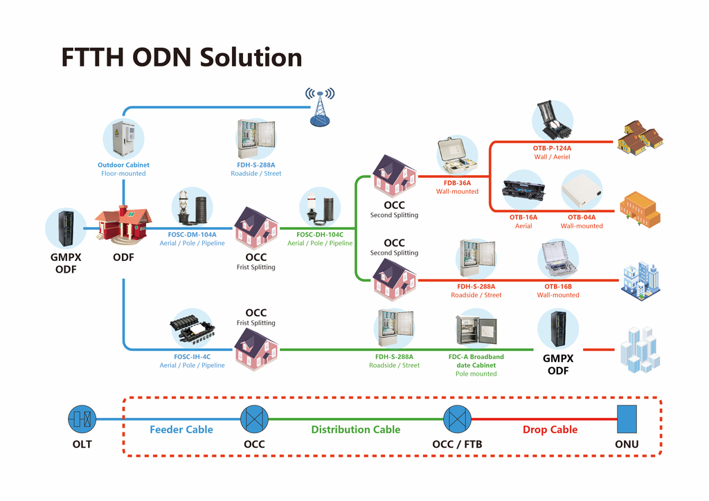
Figure 1. Typical FTTH architecture and the main passive-network nodes from the OLT to the subscriber premises.
2. Why ODN Design Matters Even More in 2026
XGS-PON is no longer simply an emerging option for new FTTH builds. It is increasingly part of mainstream high-capacity access deployment. At the same time, the industry is already preparing for the next stage: 50G-PON is moving through the acceleration and early-deployment phase, while FTTR and 10-gigabit all-optical networking are expanding the role of fiber deeper into homes, campuses and enterprise environments.
For network builders, this means that upgrading active equipment alone is not enough. The ODN installed today may be expected to support higher bandwidth, more subscribers and different service architectures in the years ahead. Cable routing, splitter architecture, the number of connection points, enclosure capacity, passive-component loss and installation quality all affect how much room the network has to evolve.
When planning a new build, it is therefore worth asking a question beyond today’s subscriber count: if bandwidth increases, more users are connected or the split architecture changes, will the passive network still have enough capacity and optical margin?
3. Five Questions to Answer Before an FTTH Project Starts
Who are you covering? Confirm homes passed, expected take rate and user distribution. A dense urban development and a low-density rural area should not be designed in the same way.
Where will the network run? The availability of existing ducts, poles, handholes, manholes and building entry points can directly affect both construction cost and schedule.
Where will splitting take place? Centralized splitting is easier to manage from fewer locations, while distributed splitting moves the split closer to subscribers. The right choice depends on density, distance and the maintenance model.
How much spare capacity should be left? Enclosures, fiber counts, ports and optical budget should not be sized only for Phase 1. Adding capacity after the network is live is usually more disruptive than reserving it sensibly at the beginning.
Who will maintain the network? Traditional fusion-spliced ODNs work well where skilled splicing teams are readily available. Where field labor is expensive or technician skill levels vary, pre-connected solutions may offer a stronger operational advantage.
4. A Higher Split Ratio Does Not Automatically Mean a Lower-Cost Network
Split ratios such as 1:8, 1:16, 1:32 and 1:64 are common in FTTH networks. It is tempting to assume that a higher ratio is always more economical because one PON port can serve more subscribers. In practice, the trade-off is more complicated.
As the split ratio increases, splitter insertion loss also increases. The link must also absorb fiber attenuation, connector loss, splice loss and a practical engineering margin. The split ratio should therefore be derived from subscriber density, distance, the selected PON class and the complete optical power budget—not chosen as an isolated number.
Total ODN Loss ≈ Fiber Loss + Splitter Loss + Connector Loss + Splice Loss + Other Passive Losses + Engineering Margin
A useful rule is to avoid designing only for a link that works ‘on paper.’ Allowance should also be made for installation variation, component tolerances, aging and future repair. This becomes particularly important on longer links and networks with higher split ratios.
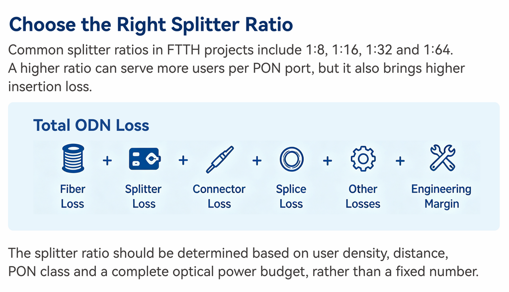
Figure 2. Split-ratio decisions should be checked against the complete ODN loss budget, not splitter loss alone.
5. Choosing a Fiber Optic Splice Closure: Look Beyond Fiber Count
Splice closures are easy to underestimate in an FTTH project. Fiber capacity is usually the first specification people compare, but field usability also depends on cable-entry configuration, mid-span access, fiber-storage space, sealing design, installation method and whether the closure will need to be reopened repeatedly.
At feeder or trunk branching points, the goal is not simply to fit today’s fibers into the enclosure. The closure should also allow technicians to add branches later without unnecessarily disturbing fibers that are already in service.
CQT GPJ09-5829 is a dome-type fiber optic splice closure supporting up to 288 splices, with seven cable ports and IP68 protection. It can be used for wall, aerial, pole-mounted and buried installations.
CQT GPJ09-6809 is a horizontal splice closure designed for branching and mid-span applications. It supports up to 144 splices, provides IP68 protection, and can be installed on walls, aerial routes, in ducts or by direct burial.
In practice, it is better to evaluate current fiber count, branching method, future expansion and maintenance frequency together rather than comparing capacity alone.
6. Distribution Boxes and Distribution Nodes: Design for the Fifth Visit, Not Just the First Installation
Once an FTTH network is live, the most common work is usually not rebuilding it. Technicians are more likely to activate new subscribers, move ports, locate faults and expand capacity. That is why a seemingly simple fiber distribution box can have a direct impact on long-term O&M efficiency.
A good distribution point should make fiber routing easy to understand, ports easy to identify and maintenance possible without disturbing the entire fiber bundle. Material and protection level should also match the installation environment, whether the enclosure is indoors, in a corridor, on a pole or fully exposed outdoors.
CQT GXF5-53 Series fiber distribution hubs are designed for centralized fiber distribution and management between feeder and distribution networks, with multiple capacity options.
CQT GF-KSW Series fiber distribution boxes support FTTH splitting and distribution and can be configured with different fiber capacities and PLC splitter arrangements.
If subscribers will be activated in phases, port organization and fiber storage deserve particular attention. A box that is convenient on the first installation should still be convenient when it is opened for the fifth service visit.
7. The Last Mile: Why Pre-Connected FTTH Is Getting More Attention
The last mile has a practical challenge: there are many access points, many repetitive tasks and considerable variation in field workmanship. Traditional fusion splicing is mature and flexible, but it requires splicing equipment and trained technicians.
Pre-connected FTTH moves more connection work into the factory and reduces the number of fusion-splicing operations required in the field. The point is not to eliminate fusion splicing everywhere. It is to simplify field work where faster and more consistent installation matters.
CQT GP62DW pre-connected terminal boxes are designed for fast outdoor connection, helping reduce field splicing and supporting project-specific pre-connected interfaces and splitter configurations.
CQT GP62DW-7 FTTH terminal boxes can support PLC splitters and multiple drop-cable outputs for subscriber access and final distribution.
For equal-ratio splitting, CQT pre-connected solutions can be configured with 1×8 and 1×16 splitters.
For unequal-ratio splitting, CQT Marvel solutions can support configurations such as 1×5, 1×9 and 1×17, depending on the network design.
CQT’s Gen-II Marvel pre-connected solution uses the compact Sticklok locking-connector concept. It is worth evaluating for projects where labor costs are high, rapid mass activation is important, or handhole and terminal space is limited.
Pre-connected does not mean ‘no planning required.’ Cable lengths, connector interfaces, node locations and inventory still need to be defined in advance. With fewer field operations, accurate front-end planning becomes even more important.
8. Fusion-Spliced or Pre-Connected ODN? A Practical Way to Decide
| If the Project Prioritizes… | Consider… |
| Flexible field adjustments and an experienced splicing workforce | Traditional fusion-spliced ODN |
| Less field splicing and faster repetitive installation | Pre-connected ODN |
| Routes and cable lengths that often change on site | Traditional fusion-spliced architecture |
| High field-labor costs or uneven technician skill levels | Evaluating a pre-connected architecture |
| More modular maintenance for selected access sections | Pre-connected architecture as one option |
The two approaches are not mutually exclusive. A project may use conventional fusion splicing in feeder and trunk sections while introducing pre-connected products closer to the access side. The right answer comes back to the same questions: where are the costs, where are the installation bottlenecks, and who will maintain the network?
9. Different Deployment Environments, Different Priorities
Urban networks: High user density often comes with limited duct, handhole and building space. Compact products, higher port density, clear fiber management and fast activation become more important.
Rural networks: Longer distances, lower subscriber density and more aerial construction put greater emphasis on route economics, weather resistance, sealing, cable protection and efficient branching.
MDUs and apartment buildings: Space and routing are constrained from the building entrance through floor distribution to each unit. Terminal-box size, bend-radius control, labeling and relevant building requirements should be considered early.
Underground networks: Duct capacity, pulling distance, handhole/manhole space and water sealing are key considerations.
Aerial networks: Mechanical loading, pole hardware, UV exposure, wind, rain and long-term outdoor exposure require more attention.
10. Problems That Are Better Solved Before Construction
- The split ratio has been decided, but no one has completed the full optical power budget.
- A splice closure is purchased by fiber count alone, only for the team to discover on site that the cable-entry arrangement does not fit the route.
- An enclosure is sized exactly for Phase 1, leaving no room for later subscribers or port changes.
- Construction is complete, but fiber cores, splitter ports and subscriber IDs have not been documented consistently.
- A drop-cable route is shortened at the expense of proper bend radius or mechanical protection.
- A pre-connected solution is selected without confirming cable lengths and interfaces, resulting in field rework.
- Testing is completed, but the results are not mapped back to the correct route, fiber and port.
Many FTTH problems that appear later are not product failures. They are the result of information not being aligned early enough. If design, procurement, construction and O&M each focus only on their own part of the project, the network may work—but still be unnecessarily difficult to maintain.
11. A Simple FTTH Deployment Checklist
| Stage | What to Confirm |
| Planning | Coverage, user density, take rate, target bandwidth and future expansion |
| Design | Topology, splitter location, split ratio and optical power budget |
| Site survey | Ducts, poles, handholes/manholes, building entry points and construction constraints |
| Materials | Cable lengths, closures, distribution boxes, splitters, connectors and accessories |
| Installation | Pulling tension, bend radius, sealing, fiber storage, fixing and labeling |
| Testing | Optical power / insertion-loss testing and OTDR testing where required |
| As-built records | Routes, fibers, ports, node IDs and test data |
| O&M | Spare capacity, repair method, spare parts and future expansion process |
12. What Can CQT Provide for FTTH Projects?
CQT has long focused on optical communication infrastructure and ODN/FTTH products. Our portfolio covers fiber optic splice closures, distribution boxes, terminal boxes, distribution hubs, indoor and outdoor fiber cables, connectors, pedestals and manholes, supporting the network from feeder and distribution sections through to subscriber access.
For project customers, however, the product catalog is only the starting point. The real value comes from matching the right product to the network architecture, installation environment, required capacity and construction method.
- Traditional fusion-spliced, pre-connected and Gen-II Marvel ODN solutions can be selected according to project conditions.
- OEM/ODM support is available for requirements such as branding, dimensions, splitter configuration, connector interfaces and selected structural customization.
- CQT has product and material testing capabilities for mechanical performance, optical performance and environmental reliability.
If you are planning a new FTTH build or upgrading an existing ODN, start by defining the topology, subscriber scale, splitting method, installation environment and major field constraints. Once those inputs are clear, component selection becomes much more straightforward.
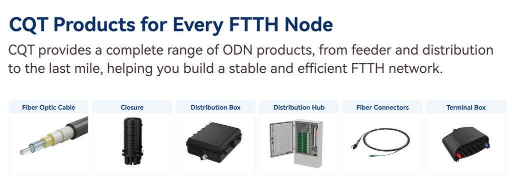
Figure 3. CQT passive FTTH/ODN products can be applied across feeder, distribution and subscriber-access sections.
13. FAQ
Are FTTH and ODN the same thing?
No. FTTH describes the fiber-to-the-home access architecture. The ODN is the passive optical distribution network between the OLT and the ONT/ONU.
Does every FTTH network need a 1:32 or 1:64 split ratio?
No. The split ratio should be determined by subscriber count, distance, optical power budget, equipment specifications and the overall network plan.
Is a higher-capacity splice closure always better?
Not necessarily. Fiber capacity is only one factor. Cable entry, branching method, available installation space, maintenance frequency and future expansion also matter.
Is pre-connected FTTH always better than fusion splicing?
No. Pre-connected solutions are well suited to reducing field splicing and improving repetitive installation efficiency, while fusion-spliced networks generally provide greater flexibility for on-site changes and complex routes.
Does an XGS-PON upgrade require replacing the entire existing ODN?
Not necessarily. Whether the existing ODN can be reused depends on its optical budget, passive-component performance, wavelength coexistence plan, connection quality and the actual network design.
14. Conclusion
A well-built FTTH network should not only look organized on the day construction is completed. Years later, when new subscribers are added, faults are traced or the network is upgraded, it should still be easy to understand and easy to work on.
That is why the most valuable FTTH decisions connect front-end design with long-term operation. Where to split, where to place closures and distribution boxes, how much capacity to reserve, and whether to use fusion-spliced or pre-connected access should all serve the same goal: a network that runs reliably and is easier for the next technician to maintain.