
Broadband access comes with a dense vocabulary, and the terms do real work. They show where a function sits in the network, where the active domain ends and the passive one begins, and what a particular product is expected to do. FTTx describes how far the optical fiber reaches: a node in FTTN, a curb or cabinet in FTTC/FTTCab, a distribution point in FTTdp, a building in FTTB, the subscriber’s home in FTTH, or even an individual room in FTTR.
This guide follows an FTTH connection from the wider broadband access network through the central office and OLT, across the passive ODN—including the ODF, feeder and distribution cables, FDT/FDH, FOSC and FDB/FAT—and finally to the ONU or ONT. It explains what each term means and where the product categories overlap. CQT focuses on the passive physical layer of the FTTH Optical Distribution Network: from optical distribution at the central office (CO) to the passive hand-off on the subscriber side, excluding the active OLT and ONU/ONT.
Zooming Out before Zooming In
The Internet is not one enormous network operated by one organization. It’s a network of interconnected networks, including access networks, metropolitan networks, national and international backbones, data-center networks and content-provider networks. A simplified end-to-end journey can be shown as: User device → Home network → ONT/ONU → ODN → OLT at the Central Office → Aggregation network → BNG/BRAS → Metro/Core network → Backbone Network → Destination network (Core, BRAS, …) → Server
When a user opens a website, sends a message or starts a video, the device does not send the information as one continuous block. The data is divided into smaller units called packets. Each packet carries part of the information and a header that tells network equipment where it is going and how it should be handled.
The request then enters the access network. In an FTTH connection, packets pass through the home router or residential gateway, the ONT/ONU and the passive optical network before reaching the OLT. Aggregation equipment combines traffic from multiple OLTs and access sites onto fewer, higher-capacity links. The operator manages each subscriber’s session, address, service and traffic policies before forwarding the traffic deeper into its network.
From there, routers move each packet toward its destination. At every hop, a router reads the destination IP address, consults its routing information and forwards the packet onward. The packet may cross backbone links, peering connections or Internet Exchange Points before entering the destination network, where the original request is reassembled and a response is sent back. There is no universal center that “searches the Internet”; each router makes a local forwarding decision using the routes available to it.
Central Office and OLT: The Starting point of PON
A Central Office (CO) is the local facility from which an operator serves a defined geographic area. Depending on the country and operator, it may also be called an Exchange, Local Exchange or Point of Presence (PoP). There is no universal service radius: coverage depends on network topology, fiber routes, the optical loss budget, the splitter arrangement, subscriber density and the location of other access sites.
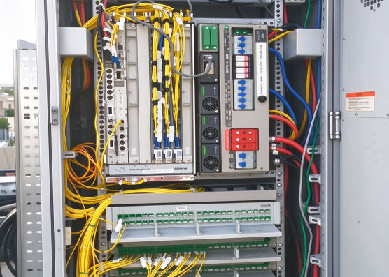
The CO is where the local access network meets the operator’s upstream transport network. Its key active component is the Optical Line Terminal (OLT), which converts traffic from the aggregation network into the PON signals sent toward subscribers and performs the reverse conversion for upstream traffic.
The OLT is the network-side root of the PON. It runs the PON protocol, controls communication with connected ONUs, allocates upstream transmission opportunities and supports network management and maintenance. Each OLT has one or more PON ports. From each port, a fiber enters the passive ODN, where optical splitters divide the path among multiple ONUs or ONTs. A complete PON system therefore comprises the OLT, the ODN and the connected ONUs.
| Category | Term | Full name | In plain English |
| Facility | CO | Central Office | A local telecom facility containing access, optical-distribution, transmission and supporting equipment. |
| Facility | Exchange | Telephone / Local Exchange | A common British and international term for a local telecom facility, broadly equivalent to a CO. |
| Facility | PoP | Point of Presence | A site where an operator installs equipment and connects to its wider network; not every PoP serves subscribers. |
| Access equipment | OLT | Optical Line Terminal / Termination | The active network element forming the network-side root of one or more ODNs. |
| OLT interface | PON Port | Passive Optical Network Port | The OLT optical port from which one PON tree begins and connects to the ODN. |
| Network side | SNI | Service Node Interface | The interface connecting the optical access network to the operator’s services and upstream network. |
| Network side | NNI | Network-to-Network Interface | A general term for an interface connecting the OLT or access network to upstream equipment. |
| Passive network | ODN | Optical Distribution Network | The passive point-to-multipoint fiber infrastructure connecting the OLT to its ONUs. |
| Direction | Downstream | OLT-to-ONU transmission | Traffic travelling from the OLT toward the connected ONUs or ONTs. |
| Direction | Upstream | ONU-to-OLT transmission | Traffic travelling from the ONUs or ONTs back toward the OLT. |
| User endpoint | ONU | Optical Network Unit | The user-side network element terminating a leaf of the ODN. |
| User endpoint | ONT | Optical Network Terminal / Termination | An ONU serving a single subscriber, commonly a home or business. |
From ODF to FDT/FDH: Primary Optical Splitting
The OLT’s PON ports connect by patch cords to an Optical Distribution Frame (ODF), which terminates, splices, patches and organizes the fibers before they leave the building. From the ODF, the outside-plant section of the ODN begins with the feeder cable, which carries the signal from the Central Office to a field distribution point such as an FDT or FDH.
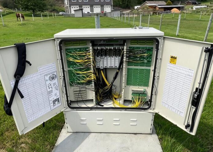
At the FDT/FDH, the feeder side meets the distribution side. Feeder cables concentrate capacity between the Central Office and a limited number of field locations, while distribution cables spread that capacity through neighborhoods, streets or buildings toward smaller access terminals. Put simply, the feeder network carries fibers to a serving area, and the distribution network carries them through it.
The FDT/FDH is also a common location for the first-level, or primary, optical splitter. A passive splitter divides the signal from one OLT-fed fiber among several downstream fibers, allowing one PON port to serve many subscribers. The arrangement depends on the network design:
- Centralized split: a single splitter stage, such as 1:32, sits at the FDT/FDH, and each output continues on its own distribution fiber.
- Cascaded or distributed split: a smaller first-level splitter, such as 1:4 or 1:8, feeds second-level splitters closer to subscribers.
- No splitter at this point: the FDT/FDH serves mainly as a splice or cross-connect location, with splitting at the Central Office or farther downstream.
At the optical level, the topology is therefore a point-to-multipoint tree: one OLT PON port forms the root, passive splitters create branches, and the ONU / ONTs form the endpoints. The physical path can be reduced to the following reference chain:
- OLT PON Port → Patch Cord → ODF → Feeder Cable → FDT/FDH + Primary Splitter → Distribution Cable → Downstream Access Terminal → Drop Cable → ONT
Optically, the result is a point-to-multipoint tree: one OLT PON port is the root, passive splitters form the branches, and the ONUs or ONTs are the endpoints. This is a reference architecture rather than a fixed rule. Splitters can sit at the ODF, FDT/FDH, a splice closure or a downstream terminal, and a network may use one splitter stage or several.
| Term | Full name | In plain English |
| ODF | Optical Distribution Frame | The frame that terminates, organizes and connects OLT-side fibers to outgoing feeder cables. |
| Patch Cord | Fiber Optic Patch Cord | A connectorized fiber used to connect an OLT port, splitter module or ODF adapter port. |
| Cross-connect | Optical Cross-connection | A flexible connection between two terminated fiber ports, usually made with a patch cord. |
| Feeder Cable | Optical Feeder Cable | The cable running from the Central Office ODF to a field distribution point. |
| FDT | Fiber Distribution Terminal | A field enclosure where feeder fibers are connected, divided or distributed toward downstream cables. |
| FDH | Fiber Distribution Hub | A centralized fiber-management point connecting feeder and distribution cables, often through splitters. |
| Distribution Cable | Optical Distribution Cable | The cable running from the field distribution point through the serving area toward access terminals. |
| Primary Splitter | First-level Optical Splitter | The first splitter after the OLT; it divides one optical path into several. |
| Split Ratio | Optical Splitting Ratio | The number of splitter inputs and outputs, written as 1:4, 1:8, 1:16 or 1:32. |
| Centralized Split | Centralized Split Architecture | A design in which the full split is performed at one location, commonly an FDH. |
| Cascaded Split | Cascaded / Distributed Split Architecture | A design in which the split is divided between two or more locations. |
| P2MP | Point-to-Multipoint | A topology in which one OLT port serves multiple ONUs through a branching passive ODN. |
FOSC: Protecting Splices and Branches
Optical cables often have to be extended, repaired or branched, and selected fibers may need to connect to distribution or drop cables. These operations expose fibers and create permanent splice points that need protection. A Fiber Optic Splice Closure (FOSC) provides a sealed enclosure in which cables are anchored, fibers are routed and stored, and fusion or mechanical splices are organized in trays.
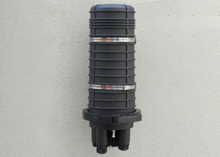
A FOSC can sit almost anywhere in the feeder or distribution network—joining cable sections, branching one cable into several routes, repairing damage or connecting selected feeder fibers to downstream cables. Its main functions are to:
- Protect splices and bare fibers from water, dust, impact and other environmental stress
- Provide cable sealing, anchoring and strain relief
- Maintain safe fiber routing and the minimum bend radius
- Store splice trays, spare fiber and cable slack
- Allow later re-entry for activation, maintenance or expansion
One of the most valuable FOSC applications is mid-span access, also known in the field as fiber extraction. Instead of cutting the entire feeder cable, the installer opens a section of sheath and accesses only the fibers needed for a local branch; the remaining fibers pass through the closure uncut. FOSCs generally use dome (single-ended) or in-line (horizontal) housings, but shape alone does not determine function. Either design can support straight splicing, branching, repair or mid-span access.
| Category | Term | Full name | Plain-English meaning |
| Enclosure | FOSC | Fiber Optic Splice Closure | A sealed enclosure that protects and manages optical-cable splices in the outside plant. |
| Joint type | Straight Splice | Straight-through Cable Splice | A splice joining the fibers of one cable section to the corresponding fibers of another. |
| Network function | Branch Splice | Branching Cable Splice | A splice that diverts selected fibers from a main cable into one or more branch cables. |
| Access method | Mid-span Access | Mid-span Cable Access | Opening a cable between its ends to reach selected fibers without cutting the entire cable. |
| Access method | Express / Tap-off | Expressed fiber or Tap-off Splice | A configuration in which most fibers pass through uncut while selected fibers are branched or spliced. |
| Cable entry | Express Port | Mid-span / Oval Cable Port | A port allowing an uncut cable loop to enter and leave the closure while remaining sealed and strain-relieved. |
| fiber management | Splice Tray | Fiber Splice Organizer Tray | A tray that holds protected splices and routes the associated fibers. |
| fiber management | Slack Storage | fiber or Buffer-tube Storage | Space for storing uncut buffer tubes and spare fiber length for future access or re-splicing. |
| Enclosure type | Dome Closure | Single-ended Splice Closure | A closure in which cables normally enter through ports in one base. |
| Enclosure type | In-line Closure | Horizontal Splice Closure | A closure generally arranged with cable entries at opposite ends. |
| Sealing | Heat-shrink Seal | Heat-shrink Cable Sealing | A permanent or semi-permanent cable-port seal formed by heating a shrinkable sleeve. |
| Sealing | Mechanical/Gel Seal | Re-enterable Mechanical Cable Seal | A reusable cable seal based on gaskets, compression parts or sealing gel. |
FDB / FAT: At Your Doorstep
As the distribution cable approaches subscribers, it reaches a smaller access point known as a Fiber Distribution Box (FDB) or Fiber Access Terminal (FAT). This enclosure forms the practical interface between the shared distribution network and individual drop cables. It may be mounted on a pole, wall or building façade, or installed in a pedestal, handhole or indoor space.
An FDB/FAT handles several last-mile functions in one enclosure:
- Terminating or passing through the distribution cable
- Splicing and organizing selected fibers
- Housing optical splitters when splitting takes place near subscribers
- Connecting fibers to adapters or pre-connectorized ports
- Securing and routing individual drop cables
- Protecting fibers and connections during installation and maintenance
FDB and FAT are overlapping commercial categories rather than strictly standardized ones. “FDB” emphasizes fiber distribution and can describe anything from a small splice-and-adapter box to a larger splitter enclosure. “FAT” emphasizes subscriber access and usually provides clearly defined drop ports. In practice, the same enclosure may be sold under either name because it combines splicing, splitting, termination and drop distribution.
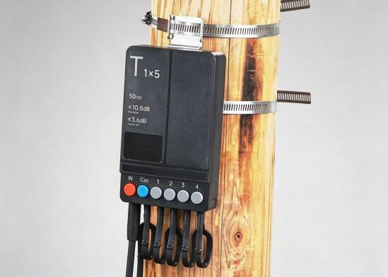
An FDB/FAT may be splice-based, connectorized or pre-connectorized. A splice-based unit requires field fusion splicing between distribution and drop fibers. A connectorized unit uses internal adapters and field-installed connectors, while a pre-connectorized unit provides factory-installed, environmentally sealed ports for faster activation. Splitters are optional: in a centralized-split network, the box may only distribute fibers from an upstream FDH; in a distributed-split network, it may house the secondary or final splitter close to the homes it serves.
| Category | Term | Full name | Plain-English meaning |
| Enclosure | FDB | Fiber Distribution Box | A box used to splice, split, terminate and distribute fibres toward subscriber drops. |
| Enclosure | FAT | Fiber Access Terminal | A near-subscriber terminal providing connection points for individual drop cables. |
| Incoming network | Distribution Cable | Optical Distribution Cable | The multi-fibre cable supplying an FDB/FAT from an upstream distribution node. |
| Subscriber connection | Drop Cable | Subscriber Drop Cable | The final optical cable connecting the access terminal to an individual home or business. |
| Passive component | Secondary Splitter | Second-level Optical Splitter | A downstream splitter used after a primary splitter in a cascaded-split architecture. |
| Connection | Adapter | Fiber Optic Adapter | A component that aligns and connects two optical-fibre connectors. |
| Connection | Drop Port | Subscriber Drop Port | A dedicated outlet for connecting one subscriber drop cable. |
| Configuration | Splice-based | Spliced Terminal | A terminal in which incoming and outgoing fibres are joined by fusion splicing. |
| Configuration | Connectorized | Connectorized Terminal | A terminal using adapters and removable fibre connectors for service connections. |
| Configuration | Pre-connectorized | Factory-connectorized Terminal | A terminal with factory-installed ports for faster plug-and-play deployment.ecatalog. |
| Protection | Hardened Connector | Environmentally Sealed Connector | A rugged outdoor connector designed to resist moisture, dust and mechanical exposure. |
| Installation | Pole/Wall Mount | Pole- or Wall-mounted Installation | Common methods for positioning an access terminal near the subscribers it serves. |
ONU / ONT: The Endpoint
At the subscriber end, the drop cable reaches an Optical Network Unit (ONU) or Optical Network Terminal (ONT). This device terminates the PON optical signal and converts it into subscriber services such as Ethernet, Wi-Fi, telephone or television. It performs the reverse conversion for upstream traffic.
ONU is the broader term for equipment terminating the user-side endpoint of an ODN. ONT usually refers to an ONU serving one home or business, while other ONU types may serve multiple apartments, tenants or business users. In everyday FTTH usage, the two terms are often used interchangeably.
The ONU/ONT is powered electronic equipment and therefore belongs to the active part of the PON system, not to the passive ODN. The ODN is the passive fiber infrastructure between the OLT and the ONU/ONT, ending at the ONU/ONT’s network-facing optical interface.
| Term | Full name | Plain-English meaning |
| ONU | Optical Network Unit | The general term for active user-side equipment that terminates a PON connection. |
| ONT | Optical Network Terminal/Termination | An ONU installed for an individual subscriber, typically a home or business. |
| SFU | Single Family Unit | A basic ONU/ONT, commonly operating as a bridge with limited gateway functions. |
| HGU | Home Gateway Unit | An ONT with integrated routing, Wi-Fi, voice and home-network functions. |
| MDU | Multi-Dwelling Unit | An ONU designed to serve multiple subscribers in an apartment or similar building. |
| CPE | Customer Premises Equipment | A broad term for powered network equipment installed at the customer’s premises. |